All the UML you need to know
By Paul Gestwicki
Introduction
This page describes the elements of the UML that I expect my students
to know. By no means does this document attempt to portray all of the
UML. Those elements described herein are those that I have found
useful in practice and those that I have seen featured in formal
and informal written communication. That is, these are the minimum
features that I consider to represent UML literacy.
Sequence Diagrams
This document is being written in Fall 2011, and we already talked about
these in class. I'm not going to invest the time in reiterating the
same content here, since you have it in your notes already.
Class Diagrams
Classes and interfaces
A class is represented by a box with up to three sections:
the top contains the class name; the middle contains the fields;
the bottom contains the methods. Consider the following Java class definition, a ridiculously-designed example that will serve to demonstrate core UML data representations. (Note that if you're one of my students and you ever turn in
programs as nonsensical as this, expect to be harassed.)
public class Example {
  private int x;
  protected int y;
  public int z;
  public Example() { ... }
  public String toString() { ... }
  private void foo(int x) { ... }
  protected int bar(int y, int z) { ... }
}
This can be represented with the following class diagram.
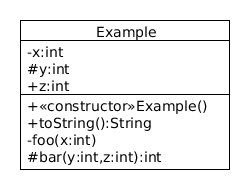
The fields and methods are annotated to indicate their access level:
plus (+) for public, minus (-) for private, and
hash (#) for protected. UML conventially uses Algol-style naming,
so variables are given as name:type and methods are
given as name(params):type, where each parameter
is, of course, a variable. In UML, metadata is often represented
through stereotypes, which are always listed
in guillemet. For
example, the fact that our
Example() method is a constructor is identified via the
«constructor» stereotype.
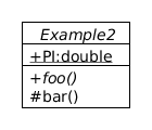
Static members in class diagrams are underlined, and abstract
elements are italicized. Here is another code and diagram example.
public abstract class Example2 {
  public static final double PI = 3.14;
  public abstract void foo() { ... }
  protected void bar() { ... }
}
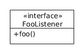
Interfaces are given the «interface» annotation, as shown below.
public interface FooListener {
  public void foo();
}
Keep in mind that UML is a communication tool, and you can omit details
that are not necessary for expressing your message. For example,
I frequently skip the middle box in UML classes since they deal with
data representation, and I'm usually more interested in capturing the
relationships among classes.
Relationships
It is the messages sent among objects that give a system dynamic behavior,
and these are represented in UML through the relationships among classes.
There are four kinds of relationships that I use regularly, shown in the
following table in order of increasing specificity. That is, the relationships
lower on the table subsume all those above them.
| Relationship | Depiction | Interpretation |
|---|
| Dependency |
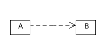 |
A depends on B
This is a very loose
relationship and so I rarely use it, but it's good to recognize and
be able to read it. |
| Association |
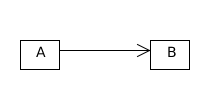 |
An A sends messages to a B
Associations imply a direct communication path. In programming terms,
it means instances of A can call methods of instances
of B, for example, if a B is passed to a
method of an A. |
| Aggregation |
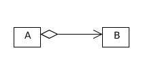 |
An A is made up of B
This is a part-to-whole relationship, where A is the whole
and B is the part.
In code, this essentially implies A has fields of type
B.
|
| Composition |
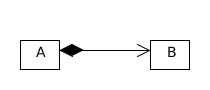 |
An A is made up of B with lifetime dependency
That is, A aggregates B, and if the A is destroyed, its B are destroyed as well. |
A useful annotation on these relationships is multiplicity, which tells
you how many of each object is involved in the relationship.
This can be a constant ("1"), unbounded ("*",
i.e., zero or more),
or a range ("2..*").
Where multiplicity is not explicit, "1" is assumed.
You can also annotate a relationship with roles to further
describe the relationship; these roles may translate into fields in the
implementation.
For example, the relationship between a player and its
achievements might be represented as follows:
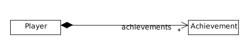
(The reader may wonder what actual data structure is used to hold the
achievements: is it an array, or a linked list, or something else?
At this level of modeling, that's probably not important. You could use UML
to show that Player aggregates a java.util.LinkedList,
and that this list aggregates Achivement objects, but unless
that's essential to your reader, you're best to skip it.)
Directionality is another important aspect of relationships.
All of my examples above have been unidirectional, but relationships
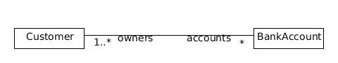
may also be bidirectional. This is shown by omitting the arrowhead. For example, the following diagram shows a case where a customer may have any number
of bank accounts, and a bank account can be owned by one or more customers.
Note that you could use the open diamond annotation to show aggregation
if you were interpreting this as a part-to-whole on either or both sides.
(This proves the fact that you cannot write a UML tutorial without
a bank account example. QED.)
Two other important relationships deal with the relationship among
classes, shown in the table below.
| Relationship | Depiction | Interpretation |
|---|
| Generalization |
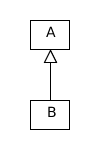 |
A generalizes B
Equivalently, B is a subclass of A.
In Java, this is extends.
|
| Realization |
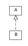 |
B realizes (the interface defined in) A
As the parenthetical name implies, this is used to show that
a class realizes an interface. In Java, this is implements,
and so it would be common for A to have the
«interface» stereotype.
|
Note that it's not mandatory
to draw these with vertical alignment, but I do recommend it to
improve readability. Most readers will conceptualize the upper class
as more general and the lower class as more specific; if you were
to invert your relationship, you would be causing unnecessary cognitive
dissonance.
Multiple representations, plus collaboration notation
In a good OO design, you have cross-module dependencies on interfaces,
not implementations. As a result, you might frequently encounter cases
as shown below, where a Button sends messages
through the ActionListener interface
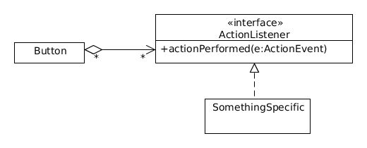
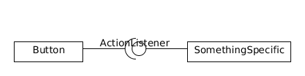
If what you're trying to express is that information gets to
SomethingSpecific from Button, then you
can use the ball-and-socket notation instead, as shown below.
This says that the communication between Button
and SomethingSpecific happens through the
ActionListener interface.
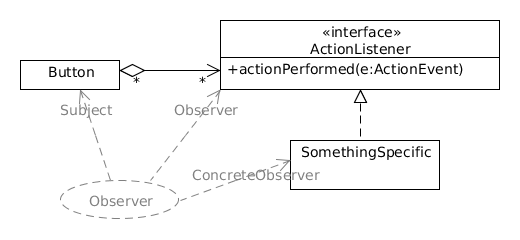
On the other hand, if the important thing to show is that this
is a reification of the
observer
design pattern, then you can use a UML collaboration to show
this. As always, it all comes down to knowing what you want to say and
then using the notation to your advantage.
Miscellaneous
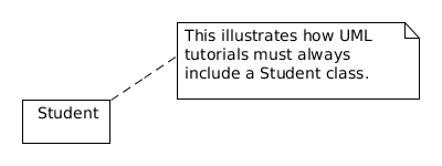
You can put a note on any part of a UML diagram. Connect the note
to the relevant bit with a dashed line, as shown in the example below.
Concluding Remarks
The UML is a massive specification, and I've only showed one or two
kinds of diagrams above. These are the diagrams I encounter most often
in research, on the Web, and in print. For your next steps,
I would recommend learning
state machine diagrams,
activity diagrams, and
use case diagrams.
One of the most useful UML resources I have found online is Allen Holub's UML Quick Reference—great
for getting a refresher or a birds-eye view on a diagram type.
All of the diagrams above were created with UMLet, an amazing and free tool for rapidly creation of UML diagrams.

All the UML you need to know by Paul Gestwicki is licensed under a Creative Commons Attribution-NonCommercial-ShareAlike 3.0 Unported License.